

Our eSTS Waits For The Perfect Moment To Transfer
The phase of the voltage waveform from each power source is sensed continuously, and the phase difference is known at all times, so that it can be used when the transfer is necessary. The method and apparatus monitors the voltage from the first power source, and initiates the transfer from the first power source to the second power source in response to an unacceptable condition from the first power source. The second power source is connected only after waiting for a period of time corresponding to the appropriate time delay. When Source 1 and Source 2 are out of phase and the transfer switch performs a ¼ cycle transfer, the transformer is already magnetized. The magnetic flux of the transformer must be balanced going from one source to another. Nothing could be simpler than a time delay that stays inside of the CBEMA curve.The Effect of Under Voltage Set Point on Transformer Inrush
Dynamic Phase Compensation Transfer Introduction
Dynamic Phase Compensation Transfer is a technique invented by LayerZero Power Systems to minimize transformer saturation current during out-of-phase static transfers on the primary side of transformers. This review outlines the effects of varying the under-voltage transfer set point on the amount of saturation current drawn by the downstream distribution.Background
Static transfer switches have been used effectively to provide redundancy to power distribution paths that feed mission critical loads. Static transfer switches (STS) may be installed on the line side or the load side of distribution transformers; each topology has its benefits and potential pitfalls. The line side STS is less expensive and takes up less floor space, watt-for-watt. However, if not properly designed and coordinated, the line side STS can have deleterious effects of its own, during out-of-phase transfer events. Since 2001 LayerZero has been a proponent of the use of low inrush distribution transformers in critical distribution systems. In 2004-05 LayerZero invented and perfected the Dynamic Phase Compensation Transfer technique to minimize the saturation current (commonly called inrush) from out-of-phase transfers. This technique has now been installed and tested in over a thousand STS systems in critical facilities. Depending on the voltage of uninterruptible power systems (UPS) that is installed as the source of power to each side of the STS, customers and their engineers have varied the under voltage (UV) set point criteria. The UV set point determines the percentage (below nominal voltage) at which transfer is initiated (away from a failing source, to the alternate available source). This paper reviews the effect of these set points on downstream transformer saturation current.Testing Apparatus and Method
| Item | Rating |
|---|---|
| STS | 600A (LayerZero eSTS model, with Dynamic Phase Compensation Transfer Enabled) 480V, 2-source |
| Transformer | 216kVA; 5.3% impedance; 5x inrush rating; 480V : 120/208V |
| Source 1 | Utility, 60.0 Hz |
| Source 2 | Generator, 59.9 Hz |
| Load | Resistive load bank; running 216kVA (100% transformer load) 260A primary current (100% load) |
Review of Results
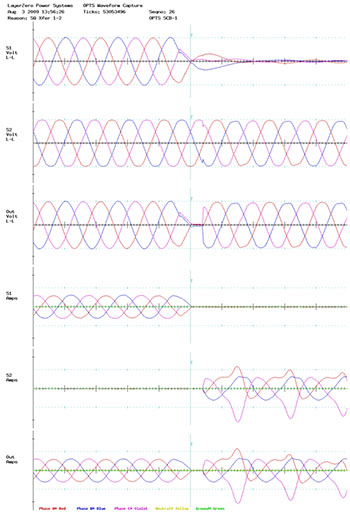
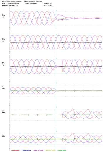
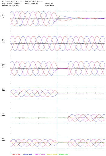
Thumbnails of the transfer waveforms of each transfer are below. The results are arranged by Phase Angle. Within each phase angle category, the waveforms associated with each of the four set points are displayed to allow for easy examination of the effect on saturation current of varying the UV set point.Select Phase Angle
Phase Angle 0°
Phase Angle 90°
Phase Angle 150°
Phase Angle 180°
Phase Angle 210°
Phase Angle 270°
Select the buttons to view different phase angles.
Transfer Waveform Thumbnails: Phase angle 0°
 UV Transfer Set point: 80% of nominal
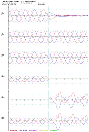 UV Transfer Set point: 85% of nominal
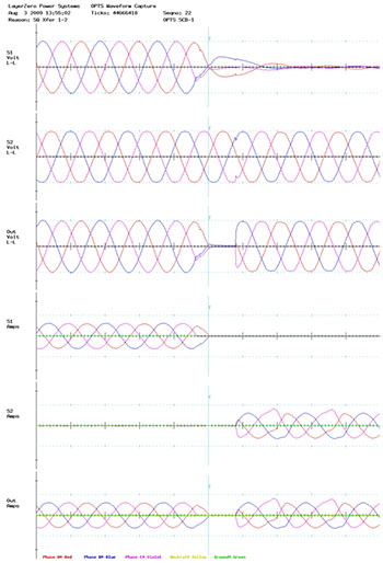
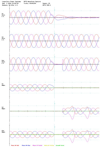
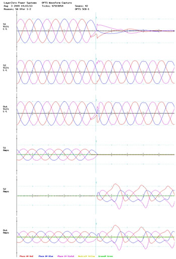 UV Transfer Set point: 90% of nominal
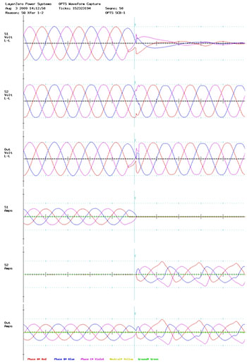 UV Transfer Set point: 93% of nominal
Transfer Waveform Thumbnails: Phase angle 90°
 UV Transfer Set point: 80% of nominal
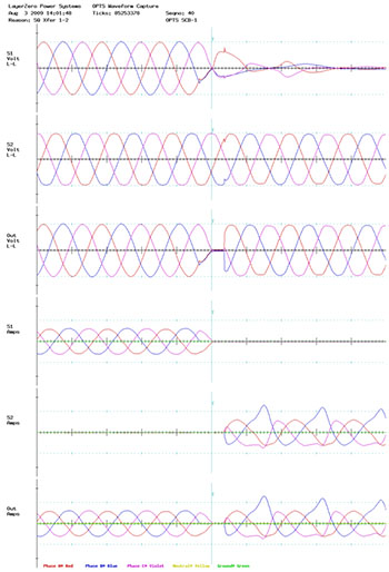 UV Transfer Set point: 85% of nominal
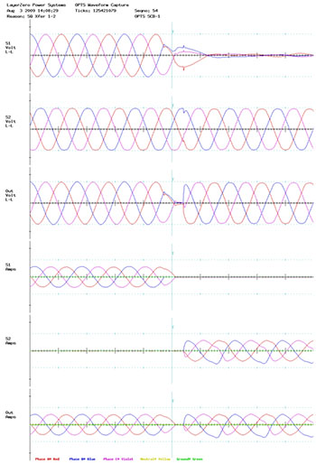 UV Transfer Set point: 90% of nominal
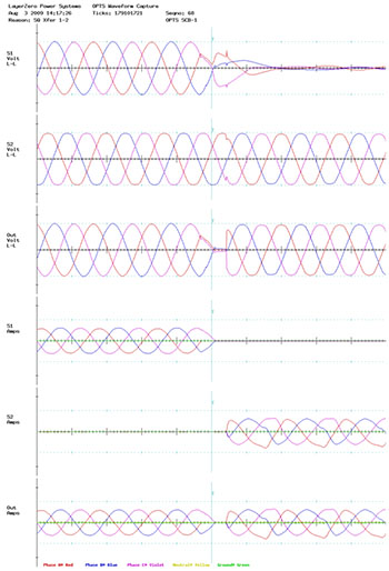 UV Transfer Set point: 93% of nominal
Transfer Waveform Thumbnails: Phase angle 150°
 UV Transfer Set point: 80% of nominal
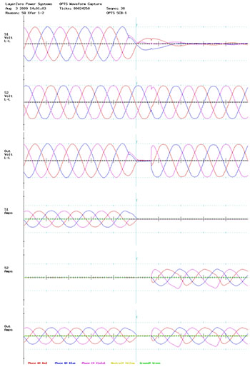 UV Transfer Set point: 85% of nominal
 UV Transfer Set point: 90% of nominal
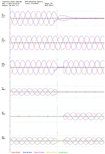 UV Transfer Set point: 93% of nominal
Transfer Waveform Thumbnails: Phase angle 180°
 UV Transfer Set point: 80% of nominal
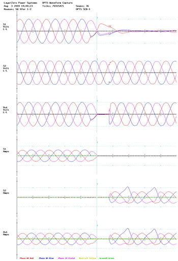 UV Transfer Set point: 85% of nominal
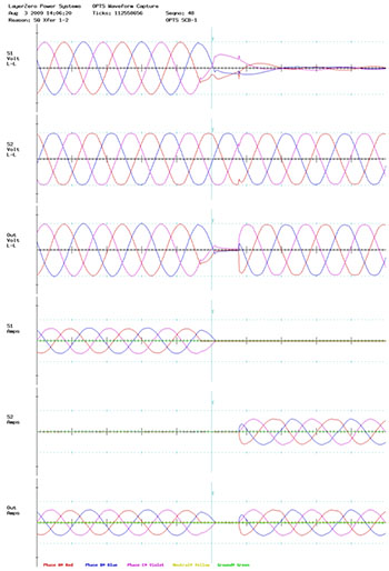 UV Transfer Set point: 90% of nominal
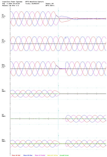 UV Transfer Set point: 93% of nominal
Transfer Waveform Thumbnails: Phase angle 210°
 UV Transfer Set point: 80% of nominal
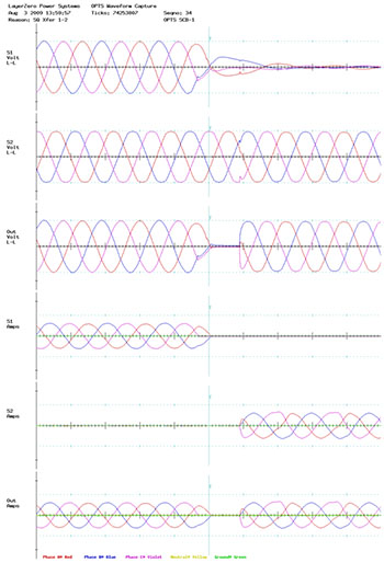 UV Transfer Set point: 85% of nominal
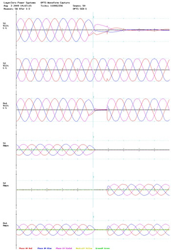 UV Transfer Set point: 90% of nominal
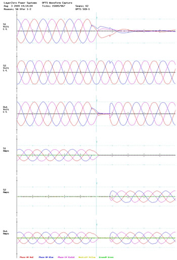 UV Transfer Set point: 93% of nominal
Transfer Waveform Thumbnails: Phase angle 270°
 UV Transfer Set point: 80% of nominal
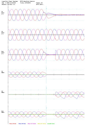 UV Transfer Set point: 85% of nominal
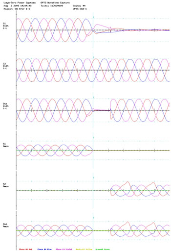 UV Transfer Set point: 90% of nominal
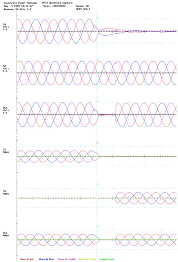 UV Transfer Set point: 93% of nominal
Summary and Conclusion
From a review of the thumbnails, it is apparent that as the UV set point is made tighter (closer to nominal), the amount of saturation current is reduced for all values of phase angle difference between the sources.